
The preamp in L Series Tribute basses is functionally equivalent to the US preamp. The circuit itself is the same, though the components are usually of lesser tolerance or non-optimal voltage rating. This lesser tolerance, taken in combination across the entire circuit, can cause value swings of 10% or more. What this means is that the preamp can be somewhat noisy; that hiss that can sometimes be heard. A noisy preamp is problematic if you're doing studio work.
Here's what the preamp looks like. The big "tell" is that the resistors are plain 5% tolerance carbon resistors rather 1% tolerance metal film resistors. The caps and chip will usually be different as well.

This will not be a how-to or a tutorial. As such, there will be certain things that you're just going to have to know or learn. Like how to solder to a circuit board. Equally important, you'll need to know how to desolder from a circuit board. Fortunately, there are lots of places on the Internet to pick up this knowledge and there are lots of ways to practice. I'll link in a few of these in a bit.
There will also be a few tools that you'll need. None are terribly expensive, but all are required. They're also handy to have around for small electronic tasks.
You're also going to need a target for this job; the preamp in your bass. Yup, that means that your bass will be out of commission for the duration of the retrofit. Unless things get terribly screwed up, it should only be a few hours. If you've done this kind of thing before and your skill level is high, a couple hours ought to take care of it.
READ AND UNDERSTAND THIS ENTIRE ARTICLE BEFORE YOU DO ANYTHING!
Covering my fanny:
- This article involves the use of hand tools and a soldering iron. Be sure to read and follow all the instructions that come with your tools, particularly safety instructions. Be sure to wear proper eye protection and work in a well ventilated work space. BassesByLeo will assume that you know how to properly and safely use these hand tools and the soldering iron.
BassesByLeo assumes that you have the ability to read and follow directions. BassesByLeo also assumes that you possess enough common sense to keep yourself out of trouble, or failing that, have the common sense to get help when it is warranted.
BassesByLeo will not be held liable for any injury or damage of any kind to any person, animal, or object as a result of the information provided in this article. You, the reader, take sole and complete responsibility for use of the information presented here. You, the reader, take sole and complete responsibility if you damage something, burn or otherwise injure yourself, burn or otherwise injure an animal, burn your home or location down, or reduce the value of your most prized guitar or bass as a result of the information provided in this article.
You, the reader, take sole and complete responsibility for any effect to your instrument's warranty caused by performing this upgrade. You, the reader, understand and accept that this upgrade may void any warranty that might be in effect on your instrument.
Now that we have that out of the way, let's get to the information you're after.
Overview
- What this article describes is removing all the components from your current Tribute preamp and replacing them with higher spec components. Anyone interested in taking on this project should either have good small job soldering skills or the willingness to invest some time (and a few dollars) to learn. If this doesn't describe you, it might be better to print this information and have a trusted tech do it for you.
If you've never soldered before, I strongly encourage you to read my tutorial from years ago on point to point soldering. It's not the type of soldering that this project calls for, but the basic concepts are the same; particularly the basics of proper soldering technique. It also gives a good view of tools for the job; see Implements Of Destruction. I also strongly recommend that you view the video on desoldering. The presenter shows two methods; one using braid and the second using a suction tool. Decide which one will work best for you and go with it. Or try both, as neither is very expensive.
Buildyourownclone.com is a site that sells effects pedal kits that are clones of famous pedals. We're not affiliated in any way, but I do kinda like what he's doing. Anyway, they have a confidence builder kit that is inexpensive and a great way to get your feet wet with building to a printed circuit board. If you've not soldered before, I highly recommend that you splurge a little and build this kit. It'll be linked below.
You'll need a shopping list, and that will be linked below. It will be up to you to source components. A good local electronics shop would be a very nice thing to have, such as JK Electronics in Westminster, CA. There's also DigiKey and Mouser. If you know of another source, please chime in.
Links to outside information:
- The BassesByLeo soldering tutorial.
Colin's Lab (from AdaFruit) soldering and desoldering info.
The BYOC Confidence Booster kit.
Stuff you'll need; supplies & tools
- As I mention above, the BbL Soldering Tutorial's Implements Of Destruction is a good list to go with. The picture shows my fancy soldering station, but a simple station is really all you need. Or even just a simple iron. If you need to tool up, I'll leave it to you to do the source work. I will say this though; spending a bit extra for good quality tools will pay off in the long run. .064" wire rosin core solder should be fine for this project. I use automatic wire strippers, but something simpler is perfectly fine.
Desoldering braid as described in the desoldering demo. Link to Amazon.
Desoldering suction tool as described in the desoldering demo. Link to Amazon.
The Shopping List. This is for the actual components you'll need for the upgrade. Don't forget the 8 pin mini-DIP socket at the bottom. PDF.
Components orientation notes
IMPORTANT
- The chip (U1) and the electrolytic capacitors must be oriented correctly otherwise the preamp will not work and you might damage something.
First, the U1 chip and socket.
In this project you'll be soldering a socket to the board that will accept U1, rather than soldering U1 directly to the board. Look at the photo above of the preamp as well as the images immediately below. As viewed in the image below, notice a dimple on the lower-left corner of the chip. It might be tough to see, but there is a notch on that end of the chip as well. The dimple and notch correspond to pin 1 and must be oriented correctly. In this case, it should be oriented toward R6. The chip you buy may have a dimple like this, or it may have a notch on that end, or it may have both. What ever it has must be oriented toward R6. The socket you'll use won't have a dimple but it will have a notch, and this notch should be oriented toward R6. Here are a couple images so you know what you'll get. Note the dimple and notch on the chip and the notch on the socket. The LM4250CN chip shown below is just an example of form factor as the LM4250 has been discontinued. See the shopping list for details.


Next, the electrolytic caps.
Electrolytic capacitors are polarized, meaning that there is a positive (+) lead and a negative (-) lead. One of the leads, usually the negative lead, is clearly marked on the cap's "can" package. The board is also marked for polarity, usually the positive side. When installing be sure to feed the leads into the correct holes in the board, negative to negative and positive to positive. Here's a picture of a cap of the type you'll use here.
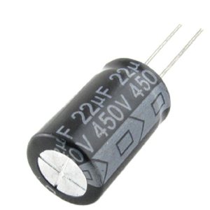
None of the remaining capacitors nor any of the resistors are polarized and can be installed in either direction.
In-process lead cleanup.
- Once you've soldered a component or two to the board, you'll trim off any excess lead length. Using a small pair of diagonal cutters (see the Implements Of Destruction), clip off excess lead length at the top of the little mound of cooled solder. Don't try to cut too short. Just at the top of the little mound.
Short & sweet.
- Open the cavity cover to expose the preamp board and make a note of which lead goes where. A photo might be handy as well. Once you're sure you've got things documented well, cut the leads to the board about 1/4" above the board and remove it from the bass.
Using all the good practices you know or have learned, desolder all components and the wire tag ends from the board.
Carefully solder in the new components and socket, paying attention to orientation and polarity as needed.
Carefully bend the pins of U1 just a little toward center. Do both sides evenly so that the pins point straight down. Making certain that it is oriented correctly, insert U1 into the socket making sure that the pins are fully inserted into the socket and don't bend.
You're working in your bass here, so be careful. From each of the leads to the preamp that you cut earlier, strip about 1/4" of insulation and tightly twist the exposed strands into a tight bundle. You can also lightly tin the bundle (optional). For each lead, insert it into the proper hole in the board and solder it just as you did the components. Note that it may take a little more time for the iron to heat the joint before applying solder. Clip off any excess lead length after soldering.
Check your work. Make sure that all your solder joints are good and that all components are in their correct locations. Verify that the electrolytic caps and U1 are oriented correctly.
IMPORTANT: Make certain that you don't drop any wire clippings into your bass' cavity. If you do, STOP and get it before going any further.
Install a battery and test. Your Tribute should now be hiss free.
As always, articles like this are a work in progress. I may pop back into it from time to time to clarify something or add info.
Ken...

